Freeform surfaces (or shells) are transforming how complex geometries are measured and analyzed, especially in advanced manufacturing. In this article, François Blateyron, Digital Surf’s senior surface metrology expert, explains how shell-based approaches enable deeper insight into surface texture, form and deviations, thus unlocking new possibilities for accurate, non-destructive characterization across a wide range of applications.
A freeform surface is represented by a mesh which is a connected set of triangles built from a 3D point cloud. In Mountains®, this is called a shell. It can be imported from STL, OBJ or PLY files or generated from CAD data, point clouds or by assembling multiple surfaces.
This type of representation captures complex or non-planar surfaces that cannot be described using the conventional surface model z=f(x,y). It opens up new possibilities for analyzing surface texture and form deviations on mechanical components and structured textures such as those produced by additive manufacturing.
Mesh representation
A shell consists of a 3D point cloud (x, y, z), where points are connected by triangles to form a mesh. This mesh must satisfy several requirements, called the manifold conditions, among which: edges can belong to only one or two triangles, triangles cannot intersect each other and elements cannot be isolated.
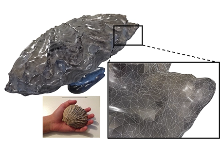
Above. Surface of a fossil captured by LiDAR, producing both a shell (mesh) and a color image. The triangular mesh can be overlaid on the shell (see zoomed detail)
Characterize internal surfaces
With traditional subtractive machining methods (grinding, lapping, milling etc.), each component is controlled before assembly. In contrast, additive manufacturing enables the production of complex, fully assembled parts, including internal features.
These internal structures can be analyzed either destructively (by cutting the part) or non-destructively using X-ray computed tomography (XCT). XCT produces a volumetric dataset from which material boundaries (e.g. metal vs air) can be extracted as a shell. The Shell Extension module in Mountains® 11 allows direct surface extraction from XCT data without requiring third-party software.
Characterize surfaces around an object
Some optical profilers include motorized rotary stages, enabling multi-angle measurements (sometimes referred to as 5-axis profilometry). By combining measurements taken at different orientations, a complete or partial shell of an object, such as a drill or worm gear, can be reconstructed and analyzed.
The Shell Topography module in Mountains® 11 assembles multiple surfaces into a shell and computes surface texture parameters directly on it. Cross-sectional profiles can also be extracted by intersecting the shell with a plane, enabling dimensional and form analysis (GD&T) using the Advanced Contour module. If only a point cloud is available, Mountains® provides meshing tools to generate a shell.
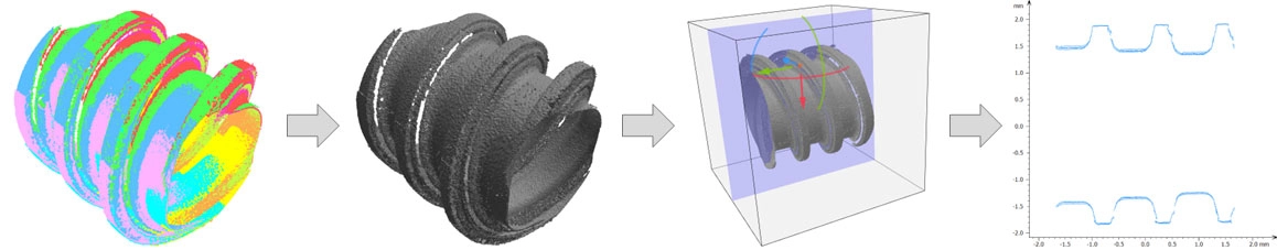
Above. Nine surfaces are assembled in 3D (left), then converted into a shell (center-left). A plane intersects the shell (center-right) to produce a Contour profile (right).
Check deviations from a nominal model
Once a measured shell (the “actual” surface) is obtained, it can be compared to a CAD model (the “nominal” surface) using the Shell CAD Compare module. Supported CAD formats (STEP, IGES, DXF) are converted into shells, aligned with the measured data, and used to calculate form deviations. These deviations are visualized as color maps, with quantitative indicators such as PV and RMS values.
Visualizing local curvature
Curvature analysis provides deeper insight into surface features, highlighting edges and local defects. Various curvature metrics can be computed and stored as point attributes, then visualized using color mapping. Additional curvature-based tools are planned for future releases of Mountains®.
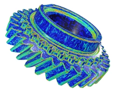
Above. Curvature mapped in color on a shell, showing the curvedness index calculated using the Cohen–Steiner tensor.
New metrological tools
Digital Surf introduced shell-based analysis several years ago through dedicated modules. In collaboration with the Centre of Precision Technologies (CPT) at the University of Huddersfield, advanced filtering and surface texture parameters have been extended to freeform surfaces.
A subset of ISO 25178-2 parameters has been adapted to curved geometries, requiring a transition from Euclidean to Riemannian geometry. These developments were first implemented in Mountains® 10 and continue to evolve. Available tools include form removal (F-operator), S-filters and various height and hybrid parameters.
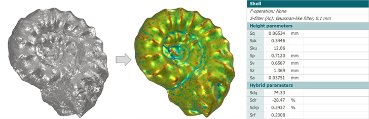
Above. Fossil shell (left), filtered using a Gaussian-like S-filter (center), with a parameter table (right) calculated from deviations shown as color mapping on the filtered shell.
Conclusion
Freeform surface analysis addresses the growing complexity of modern manufacturing and design. Mountains® 11 provides a comprehensive set of metrology tools for shells, applicable across scales, from microns to meters, and compatible with a wide range of measurement technologies.
Author : François Blateyron
Resources :
Surface texture on freeform surfaces: guide.digitalsurf.com/en/guide-freeform.html
Advanced Metrology for Freeform Surfaces, J. Jiang & P. J. Scott: www.elsevier.com/books/advanced-metrology/jiang/978-0-12-821815-0
Shell Topography module: www.digitalsurf.com/optional-modules/shell-topography-module