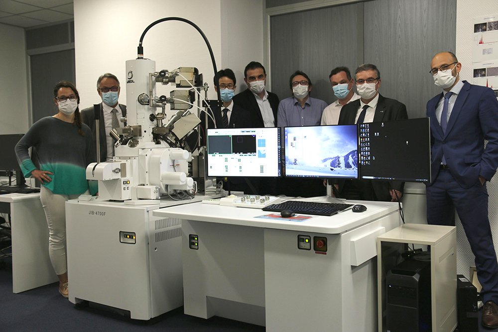
Currently, one of the major challenges in the automotive industry is the development of direct current (DC) electrical motors. A DC vehicle motor incorporates strong magnetic fields at the rotor location. The higher the magnetic field in a reduced volume, the better the engine efficiency factor. A research team based at JEOL France recently studied the composition of such a magnet using a FIB-SEM technique coupled with a specialized analysis software package.
Composition of a Cerium-alloyed Nd-Fe-B magnet
The key component of the engine is the permanent magnet located inside the rotor assembly which must have very high efficiency.
The sample studied was a Cerium-alloyed Nd-Fe-B magnet (Ce-NdFeB). The Cerium partly replaces the very expensive Neodymium rare-earth element (REE) without compromising the magnetic properties.
The research and development of this technology requires excellent knowledge of the chemical phase tomography of the magnet.
FIB-SEM machining & imagery in BSE mode
Mountains® 9 software tomography analysis is based on a series of high-resolution images representing successive cross sections taken through the depth of the sample. These different planes are produced by FIB machining and imaged in BSE mode.
BSE images are in shades of gray; the composition of the different gray levels of the image is proportional to the atomic mass of the chemical elements that make up the surface being analyzed.
The FIB/SEM technique was first highlighted by the semiconductor industry, seeking to understand the 3D complex structure and/or internal specific failure of electronic devices. JEOL (Japan Electron Optics Laboratory Company Tokyo, Japan), understood the need for Focused Ion Beam (FIB) systems early on and introduced the JIB-10 instrument in 1983.
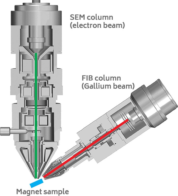
The experiment involved slicing and imaging the magnet with electrons under a strong magnetic field. This was particularly challenging since the magnetic field deflects the electrons.
The new JIB-4700F multiple-beam system from JEOL was able to overcome this difficulty. The magnet was sequentially milled using the ion beam (red arrow in Figure 1a) and imaged by the electron beam (green arrow).”
 (a)
(a) 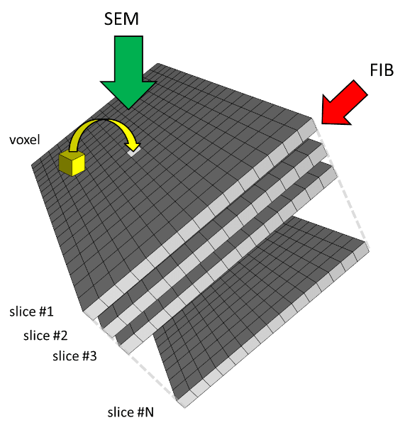 (b)
(b)
Figure 1. FIB machining & imaging in BSE mode.
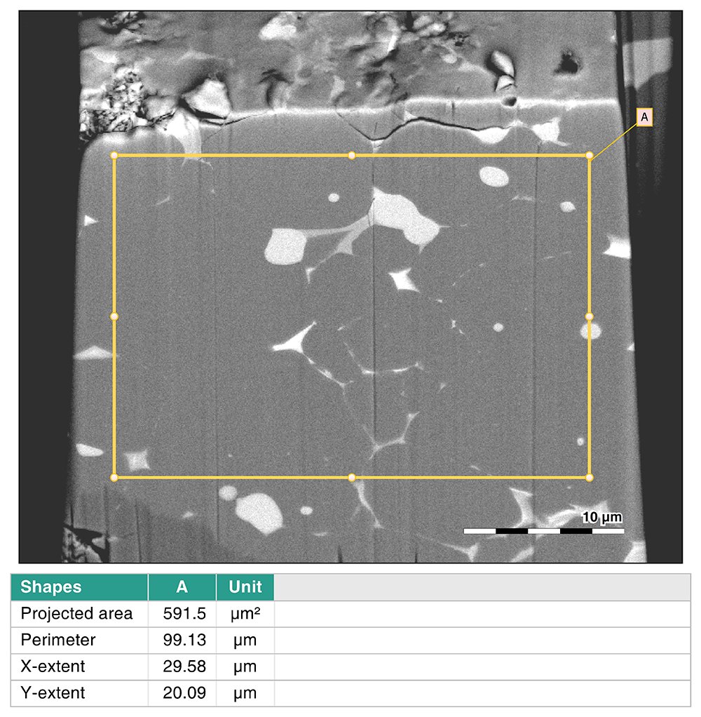
Figure 2. One of the series of BSE images with highlighted ROI.
Image processing
SMILEView™ Map software, powered by Mountains® allowed full 3D imaging and analysis of the chemical composition of the magnet material.
The chemical cube generated from the set of BSE images was segmented according to gray scale ranges corresponding to various chemical elements.
Numerous parameters including volume parameters were then calculated on the differentiated and segmented chemical elements (see Figure 3).
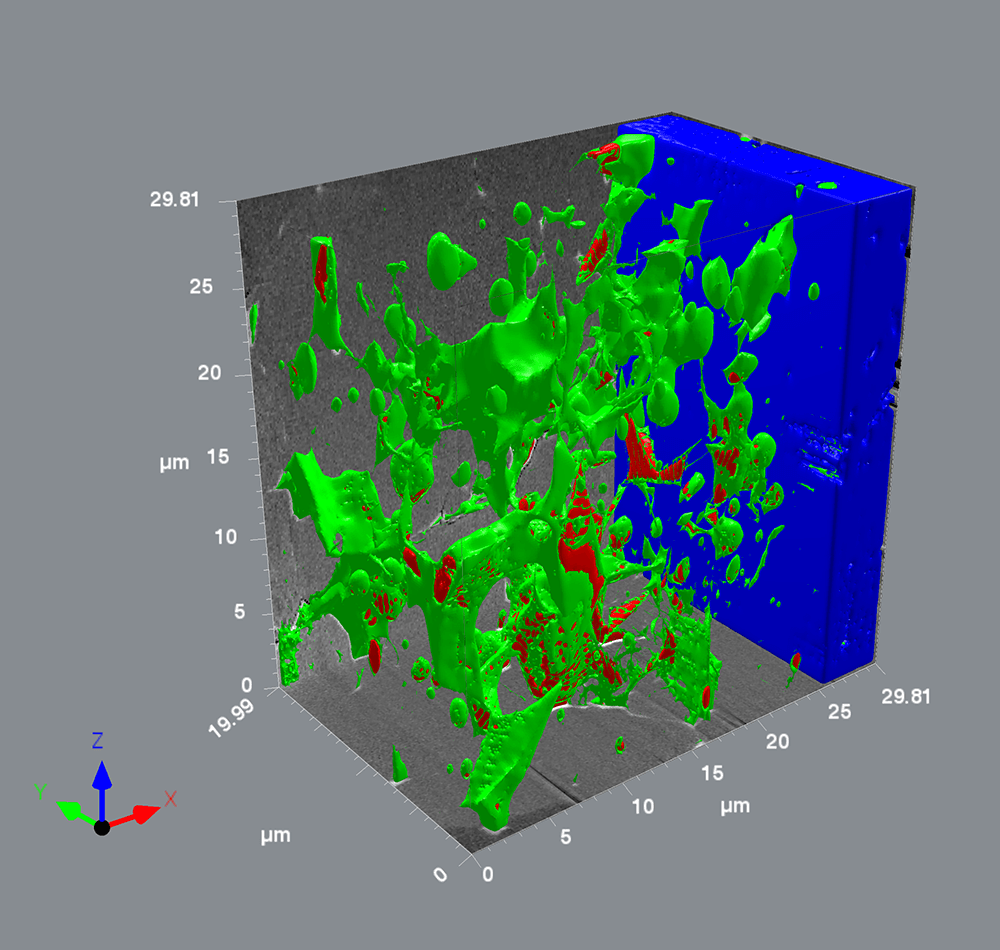
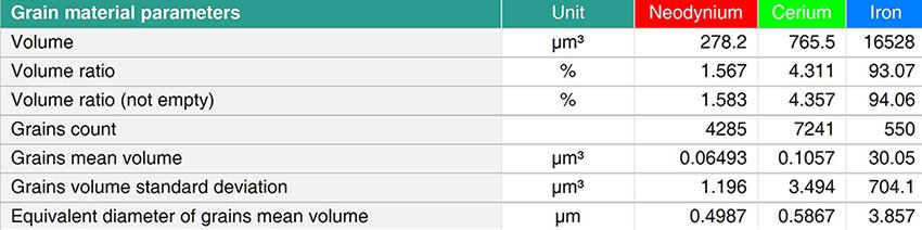
Figure 3. Visualization of BSE image stack as a cube (above) and volume parameters (right).
Once the tomogram is rebuilt, the user can virtually re-section the sample using the software, fully explore the 3D volume and get a full understanding of the magnet inner structure.
In this particular reconstruction we can observe very rich intergranular structure of Neodymium and Cerium with a low concentration of Iron in a Nd2Fe14B magnetic matrix.
Authors:
- Guillaume Lathus, Sales Director JEOL (Europe) SAS
- Franck Charles, General Manager JEOL (Europe) SAS
- Jean-Claude Menard, Senior Applications Specialist
- Special thanks to Damien Leroy (ILM)
Instruments & software used
JEOL JIB-4700F multiple-beam system + SMILEView™ Map software, powered by Mountains®