Technical drawings use a standardized graphical language that allows subcontractors to understand designers’ intent. They contain size and position specifications, dimensional tolerances and often surface texture tolerances. The technical drawing is a contract binding the parties, that acts as a reference in case of disputes about non-compliance of the produced workpiece. Digital Surf’s senior metrology expert François Blateyron explores the subject.
Surface texture specifications are indicated using the root symbol. This root symbol is defined in the ISO 1302 standard (latest version published in 2002). The new ISO 21920-1 series will soon replace this standard with several changes that may modify common practices.
Root symbol
The specified parameter should be placed under the root symbol with, at the very least, its limit value (see figure 1 below). These parameters are defined in ISO 4287, ISO 13565 or ISO 12085. Many other indications are defined by default and can be omitted on the drawing.
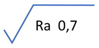
Figure 1. Specified parameter with its limit value.
When values other than the defaults are required, they must be written explicitly. For example, in figure 2. below, the bandwidth is defined with a cut-off of 0.008mm (8µm) for λs and a cut-off of 2.5 mm for λc.
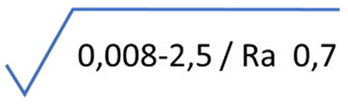
Figure 2. Specified parameter with a defined bandwith.
The specification string under the root symbol may be very long for some parameters, which makes its interpretation difficult.
Hidden defaults
The type of filter is not written in the previous example because it is the default filter (Gaussian filter, according to ISO 16610-21). The decision rule is also the default one, the 16% rule, defined in ISO 4288:1996.
All these defaults need to be understood both by the designer when creating the drawing, and by the metrologist during the verification process. Unfortunately, this is usually not the case and many misinterpretations may lead to disputes and ultimately may result in great cost.
An explanation of decision rules and hidden defaults on drawing indications can be found in this video.
Another important hidden default is the fact that parameters are calculated on several sampling lengths and averaged. By default, five sampling lengths are used. This aspect is usually taken care of by analysis software packages, but users need to understand the reasons behind it.
With five sampling lengths and a cut-off of 0.8mm, the analyzed profile will only be 4mm long (5×0.8mm), even if the user measured a profile of 16 mm. When needed, designers should adapt the evaluation length to the area of the workpiece on which they put the roughness specification, and explicitly write a longer evaluation length on the drawing.
In figure 3 (see below), for example, the evaluation length is 20×0.8mm = 16mm.
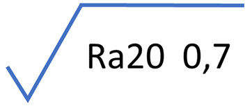
Figure 3. Example of a parameter calculated on several sampling lengths.
A video tutorial on parameters calculated according to ISO 4287 can be found here.
The new ISO 21920 will drop the average over sampling lengths for most parameters, but it will still define the evaluation length as a multiple of the cut-off, with a default number of 5xλc… unless the draft standard is changed before its publication!
New root symbols
The good news is that specifications relying on the new standard (ISO 21920) will use a modified root symbol with a dash line above the triangle. Drawings with this new symbol should be interpreted according to ISO 21920 (parts 1 to 3) whereas if the old symbol is used, drawings should be interpreted according to ISO 1302, ISO 4287, ISO 4288. Another modified root symbol, with a skewed square, refers to areal specifications according to the ISO 25178 series.
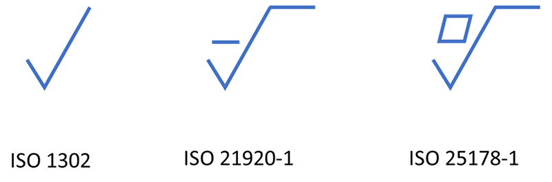
Figure 4. New root symbols and corresponding standards.
Position of the parameter
Another big change introduced by the new standard is the position of the parameter and its limit under the root symbol. With ISO 1302, the parameter was written after the oblique bar to separate it from the bandwidth specification (see figure below).
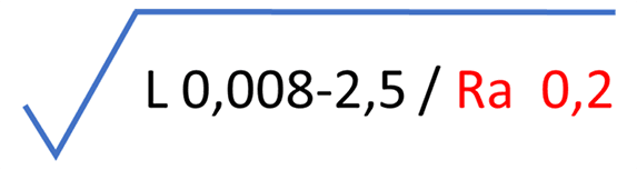
Figure 5. Expression defined by the ISO 1302 standard.
With the new standard, the parameter and the limit are written first, for better clarity. The rest is written after an oblique bar (see figure 6, below).
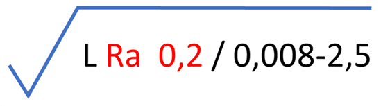
Figure 6. Updated expression defined by ISO 21920 standard.
Update your practices
These changes aim to simplify things, but at the same time they require users to update their knowledge and practices.
In order to avoid misinterpretations, the need for education and training is higher than ever. This is the mission of our Surface Metrology Guide which is freely available on the web.
Author : François Blateyron
Resources :
- Indication of surface texture on technical drawings: guide.digitalsurf.com/en/guide-indications-iso-1302.html
- ISO 1302:2002: Indication of surface texture in technical product documentation.
- ISO/DIS 21920-1:2020: Surface texture: Profile — Part 1: Indication of surface texture.
- ISO 14253-1:2017: Inspection by measurement of workpieces and measuring equipment — Part 1: Decision rules for verifying conformity or nonconformity with specifications.
- Surface Metrology Guide: digitalsurf.com/guide